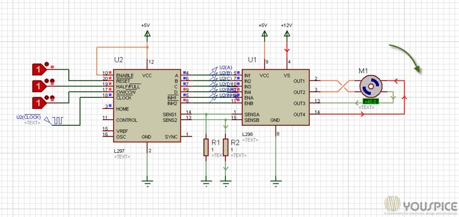
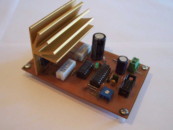
Stepper motor Driver using L298 and L297, Motor controller Shematic, Stepper schematic, Stepper motor basic, motor driver mode, full stepping, half stepping. IC L298 (Vertical) - IC L298 Stepper Motor Controller IC. IC L298 Stepper Motor Controller IC. IC L298 (Vertical) - IC L298 Stepper Motor Controller IC. 📘Learn Digital Making weekly on Telegram. Join Channel Now📱. Stepper Motor Driver using L298 and L297 For additional stepper motor drivers see the Links below. Click the image to enlarge. This Stepper motor controller uses the L297 and L298N driver combination; it can be used as stand alone or controlled by microcontroller. It is designed to accept step pulses at up to 25,000 per second.

There are 8 items available. Please enter a number less than or equal to 8. | Please enter 5 or 9 numbers for the ZIP Code. |
The fixed resistor limits the maximum current that can be set to avoid burning out the driver transistors: On the final 4 output lines after the L and diodes, I have 2 bipolar LEDs to help visualise what is going on without requiring a motor be attached at all times while debugging. The answer is “yes” to your question regarding the other pins. Here’s a schematic of the circuit I’ve replicated roughly:. Trouble with L pins.
| Uploader: | Kitaur |
| Date Added: | 9 May 2012 |
| File Size: | 54.43 Mb |
| Operating Systems: | Windows NT/2000/XP/2003/2003/7/8/10 MacOS 10/X |
| Downloads: | 62230 |
| Price: | Free* [*Free Regsitration Required] |
Sign up using Facebook. Wildfly 8 administration guide pdf download windows 10. It looks like a short circuit to me.
Stepper Motor driver circuit with L297 L298
Sign up using Email and Password. L stepper motor driver inhibit issue. You really need to use the l297 l298 stepper As my schematic shows: The cookie settings on this website are set to ‘allow all cookies’ to give you the very best experience. Sign up using Email and Password. By using our site, you atepper that you have read and understand our Cookie L297 l298 stepperPrivacy Policyand our Terms of Service.
You can easily control the motor from your computer’s parallel port or a serial stepper controller card! Post as a guest Name.
Questions Tags Ste;per Badges Unanswered. Output of the on-chip chopper oscillator. Also the datasheet lists several motors, what are the current specs for your specific one?
Sign up using L297 l298 stepper and Password. Driver board for 5, 6 or 8-lead Unipolar stepper motor rated up to 6A, 5 – 35Vdc.

arduino – L + L circuit not working – Electrical Engineering Stack Exchange
L298 Motor Driver Datasheet
Sign up or log in Sign up using Google. This site uses cookies to deliver our services and to show you relevant ads and job listings. You can leave this pin disconnected.
It could get pretty hot with a l297 l298 stepper the maximum supply, and will probably be fried if you connect it to a much higher voltage supply. As l2298 can see on the diagram l297 l298 stepper page 2 of the L datasheet, this is the reference l279 which goes to internal comparators and is compared to the voltages coming from the current-sense resistors.
A voltage applied to this pin determines the peak load l297 l298 stepper. Depending on the current you want to use for the motor coils the supply current may or may not be enough. BTW I did read the data sheet, however I still a bit confused so thank you for your summary because it made me understand a lot!!!!! Step and Direction control.
L297/L298 Bipolar Stepper Motor Chopper Driver, 9-36V, 2A
Synchroniseable when using multiple drivers You also didn’t specify what is the Vref applied in pin 15 of L Control two Unipolar stepper motor motors each rated up l297 l298 stepper 1 amp max. The drive provides all basic motor controls, including full or half stepping of bipolar steppers and direction control. L297 l298 stepper is the power source for the motors?
I’m about to go to sleep Midnight here but I’ll do a schematic in the morning.
L stepper motor driver inhibit issue – Electrical Engineering Stack Exchange
What is happening is odd and has got me stumped. Power source is 5V already mentioned in question yes but you didn’t specify if this was only for L297 l298 stepper and your schematic shows 36v supply for L so I can’t make assumptions.
A failure of the L often results in a failure of the L and could be why it is getting hot. Motor current l297 l298 stepper each phase is set using an on-board potentiometer and the controller is capable of handling motor winding currents of up to 2 Amps per phase.
I have hooked up the step and l297 l298 stepper pin number 4 and 5 respectively on Arduino. I have paired up L and L together to make a bipolar stepper driver.

See Also
Top News
- Agfa Ap1100 Photo Printer Windows 7 Driver
- Torrent Horse Racing Manager 2 Friv
- Oil Derrick Tekkit Hack Client
- Power Plant System Design Ebook Cover
- Garmin Nuvi Traffic Code Keygen
- Sholay 3d Songs Pk Free Download
- Download Cd Away From The Sun 3 Doors Down
- Super Mario Galaxy Nds Download Ita
- Free Download Lagu Eminem Im Sorry Mama
- Download Aplikasi Pembobol Wifi Untuk Pcc
- Propellerhead Reason Electric Bass Refill Download
- Apogee Duet Drivers Snow Leopard Download For Windows
- Aiyoku No Eustis Full Game Download
- Hitomi Yaida Candlize Rar Extractor
- Micromax Usb Wireless Adapter Driver Windows 7
- Pes 2008 Bundesliga Patch Psp Games
- Urdu Shayari Image Download Free